

About.
From the inception of AIS, Sine Qua Non has supplied industry leading technology to the market. All our legacy products date back to 1992 in development. Our second generation products are now comming to fruition. AISTE.ST formerly Sine Qua Non would like to take this opportunity to thank you for your continued ineterst in one of the AIS Developer Studio suite of products. We want to assure you that this product range is designed using over 22 Years of AIS experience and thoroughly tested to ensure your complete satisfaction.
AIS Developer Studio

AIS Application Specific - Message Client
AIS PMG1/2 Programmable Modulation Generator

Where did it all begin.
Between 1992 and 1995 George Fyfe was contracted as a development partner to design and produce a RF transceiver technology, which Portnet Marine Data Systems would use as an identification and telemetry RF backbone for the full length of the South African coastline.
The hardware was known as the H25. In those early days the GPS 1PPS at times just vanished, so a secondary mechanism of TDMA lock was needed and the “Semaphore” method was developed. This was based on how many H25 stations were received at a specific location. This allowed a plurality of transmitting objects to share a TDMA structure in the cell they found themselves due to the “FM capture effect”. i.e. dBm, distance and time.
At the end of 1995, Portnet hosted the IALA Aids to Navigation conference in Cape Town. It was immediately recognised that parallel marine identification technologies had been developing across the seas. This Cape Town meeting was the pre-cursor to the inaugural IALA AIS meeting held early 1996 in Sweden.
Marine Data System represented the interests of George Fyfe at the early IALA AIS working group meetings. At discussions following these meetings it soon became clear that patents were frowned upon. As George Fyfe the original developer of the “TDMA Semaphore Concept” was at that time a co-patentee with Marine Data Systems , he sold his share of the development to Marine Data Systems. George Fyfe was rewarded with a five-year restraint of trade in AIS transponder technology. The semaphore technology went on to be included in ITU-M.1371.
With the restraint on AIS transponder technology in place, George Fyfe set his sights on developing production and front line AIS test sets. This resulted in the PMG1 and the AITS-R. These units were designed and produced at a time when there was no final AIS documentation available. All documents were working group draft documents.
Sine Qua Non went on to produce these industry leading hardware items for many years. And so the story continues with AIS TEST.
AIS Developer Studio Version 2 Overview
The AIS Developer Studio is a synergistic merger of software and hardware modules to create a general AIS development, production, integration and verification environment. It provides a value added service to all users of AIS equipment. The main objective of the system is to assist in providing different test and monitoring scenarios using the PC workstation as the main control object. It does this by providing interactive modules, which have been streamlined to produce verifiable outcomes. The Automatic Identification System (AIS Class A) is defined by the IMO and has been made a carriage requirement by the latest revision of SOLAS Chapter V. This does not only require the AIS to be installed, but also to provide information used for ship navigation. The AIS has been standardised by the ITU and IEC and is subject to type approval. In order to fulfil the reliability requirements of information exchange, product pre - verification and final verification must be done at all levels of development to ensure correct AIS inter operability.
The objective for the use of the AIS Developer Studio is to create a general VDL environment using a PC and optional external RF signal generator / power pad. Where the GMSK base-band is created and VDL, VDO and VDM data are easily analysed.
Our Design Philosophy
It is the intention of AISTE.ST through the current and further development of the AIS Developer Studio suite of components to continue to supply a cost effective method for development, production, integration and verification of protocols as used by AIS, ASM and VDE. It is the intention of AISTE.ST to supply upgrades to the AIS Developer suite user group as and when they become available. Users may subscribe to this upgrade service.
AIS Marine Radio Workstation Overview
 AIS Developer Studio provides a cost effective way of adding real time AIS base-band message generation capability and VDL analysis for production, repair, development and pre-verification to any RF Signal Generator or Radio Communications Test Set.
External modulation of the RF Signal Generator or Radio Communications Test Set using AIS Developer Studio PMG2 module allows real time operational verification of AIS transponder whilst providing VDL monitoring.
Evaluation of the AIS protocol stack of the equipment under test is accomplished using this method.
Data Interfaces
The AIS Developer studio uses the PC workstation hardware equipped with interfaces that allow opperation as a VDL Analyser, Pseudo Electronic Position Fixing Device – VDO / VDM EUT / VDM RX Presentation Interface (RS232 / RS422) : EUT Ship’s Sensors Inputs (Typically Gyro, GPS, COG and ROT Sensor) (RS422) : Other NMEA-compliant ship’s navigation equipment (RS232 RS422) :
A sound card line output may be applied to an external modulation signal input on your signal generator of choice. Baseband and IQ Baseband are offered
NTP / SNTP
The AIS Developer Studio makes use of NTP/SNTP network lock to obtain a relative UTC time base. All events are time stamped with the NTP/SNTP network lock. The accuracy of the UTC time stamp is dependent on your network lock of choice.
PMG2 Modulation Waveform Generator
- AIS Message Modulation
- Base band or IQ 9.6kbits/s GMSK
- IEC 61993 10.4.1 Standard Test Signal Number 1
- IEC 61993 10.4.2 Standard Test Signal Number 2
- IEC 61993 10.4.3 Standard Test Signal Number 3
- Legacy PMG Standard Test Signal Number 4
- IEC 62287 8.3.1 Standard Test Signal Number 1
- IEC 62287 8.3.1 Standard Test Signal Number 2
- IEC 62287 8.3.1 Standard Test Signal Number 3
- IEC 62287 8.3.1 Standard Test Signal Number 4
- IEC 62287 8.3.1 Standard Test Signal Number 5
- IEC 62320 6.2.4.1 Standard Test Signal Number 1
- IEC 62320 6.2.4.2 Standard Test Signal Number 2
- IEC 62320 6.2.4.3 Standard Test Signal Number 3
- IEC 62320 6.2.4.4 Standard Test Signal Number 4
- Real-time 5 target test environment
- Real-time creation of any one of 27 M.1371-5 VDL messages
- Real Time monitoring VDM, VDO, ALR, TXT
- Includes CCITT 511 bit pseudo-random test pattern
- VDO string generation
- DSC Modulation
- V23 Modulation
- Standard DSC test signal as defined in 10.4.1
AIS VDL Analyser
- 150 tracks per timeline
- Horizontal time grid
- Vertical message grid
- Test Environment activity
- Own Profile VDO activity
- Realtime EUT VDO activity
- Realtime EUT VDM activity
- 27 M.1371-5 messages
- Realtime $AIABK monitoring
- Realtime $AIALR monitoring & manual ACK
- Realtime $AITXT monitoring
EPFD Sensor Strings (RS422 Output)
- GNS
- GLL
- GGA
- RMC
- VBW
- VTG
- HDT
- GBS
- ROT
- OSD
- DTM
- 1PPS BEEP
Standard Test Environment
- Pseudo Electronic Position Fixing Device providing exclusive direct control over GPS, COG, SOG, HDT, ROT for each individual target.
- Dynamic navigation derived from PEPFD settings.
- Detection of non valid 6 bit TEXT characters.
- Global setting of fault indication – (PC beep).
- Tracking, static and voyage data.
- Descriptions for each edit window are auto provided.
- Auto profile 5 targets using licence defaults or individual.
- SETUP 5 AIS Targets
- START 5 AIS Targets
- STOP 5 AIS Targets
-
Download
Upgrades
Waveforms
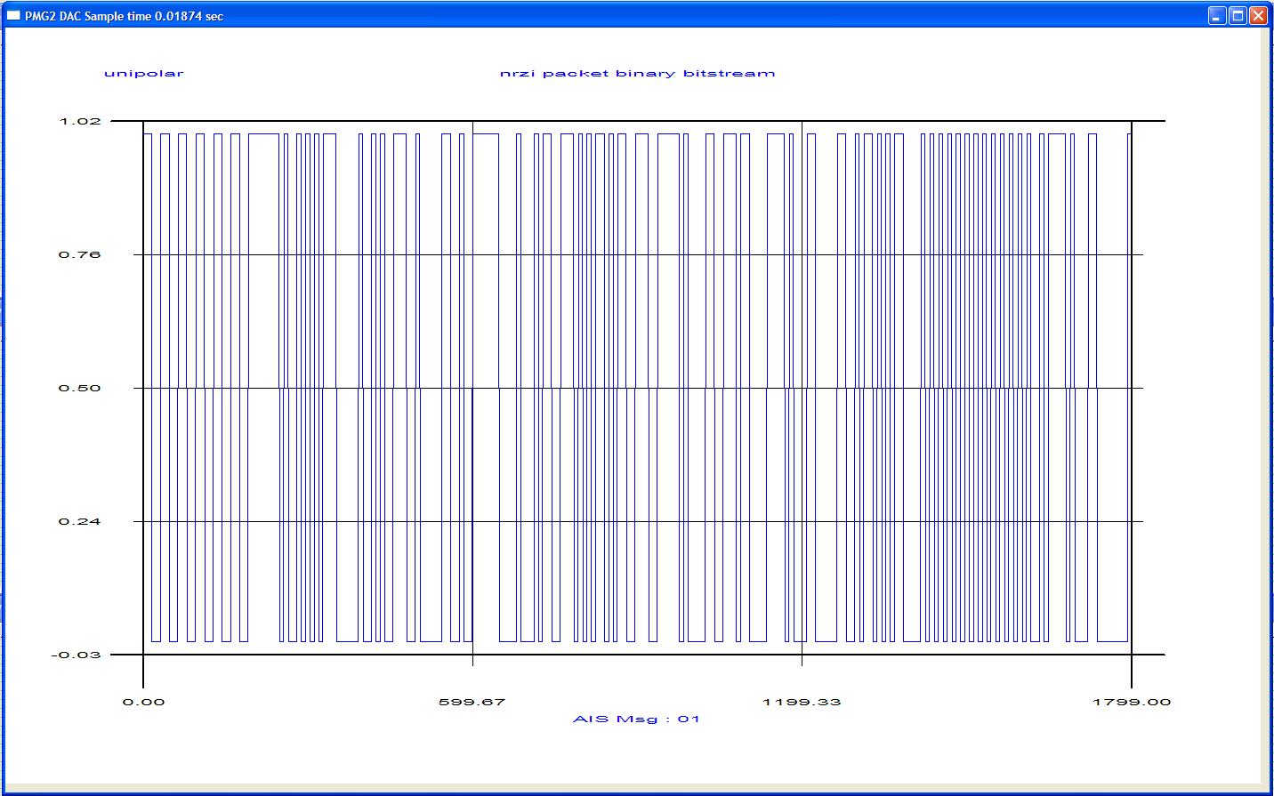
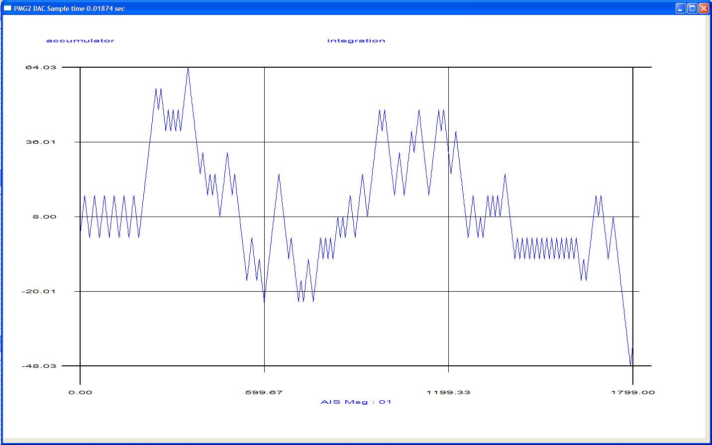
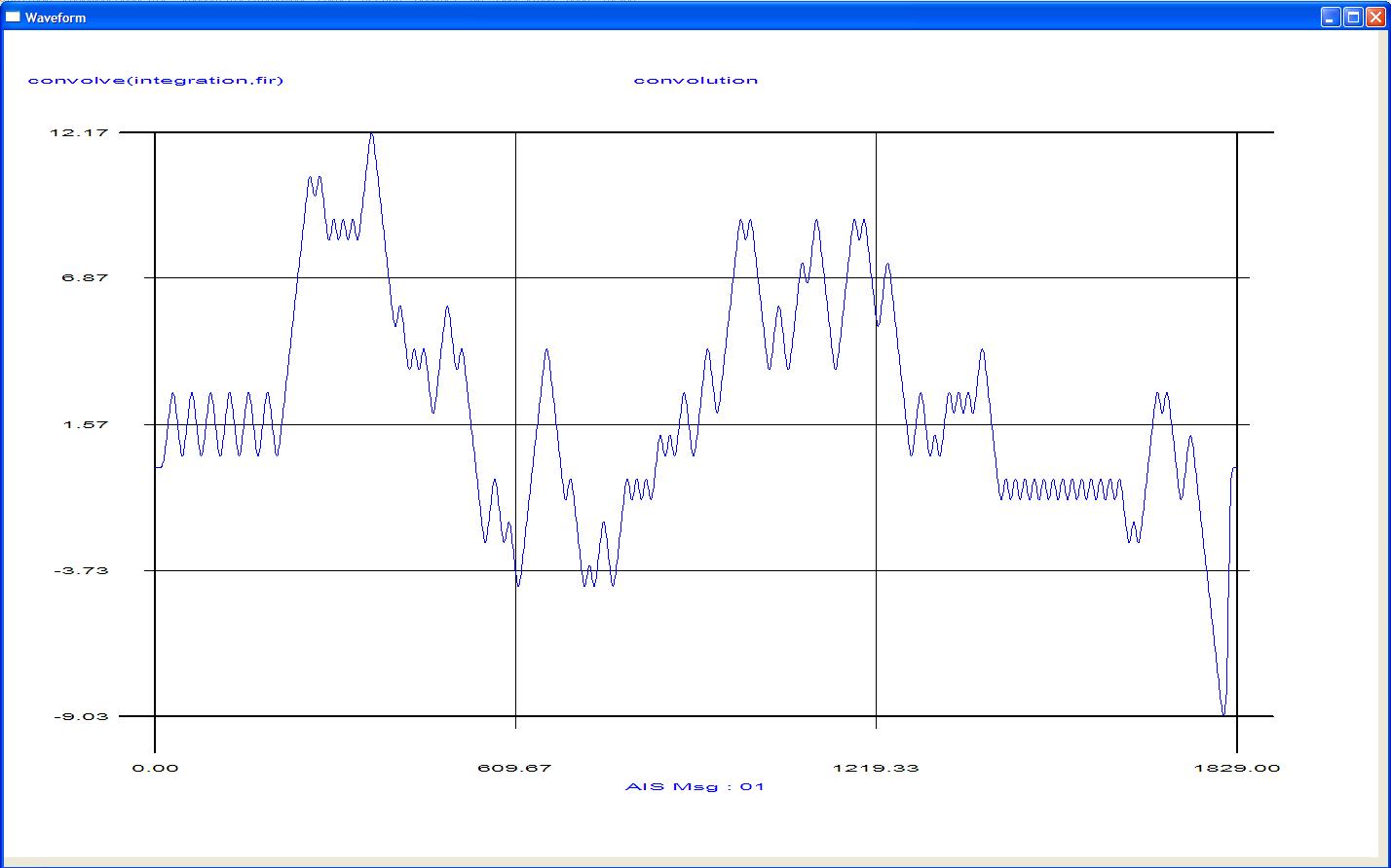
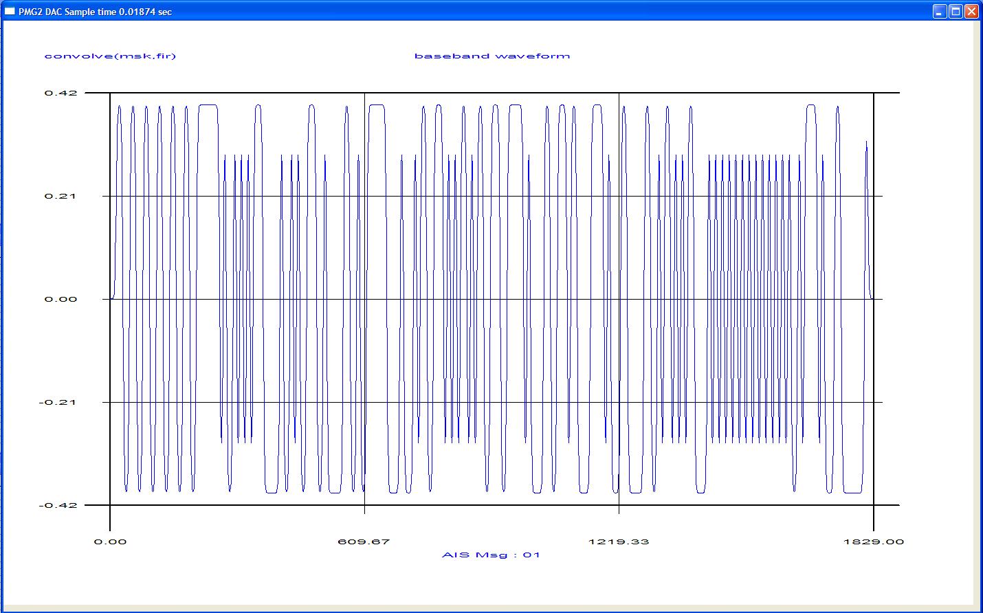
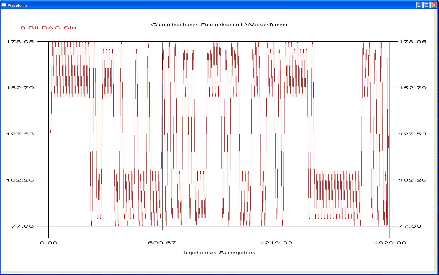
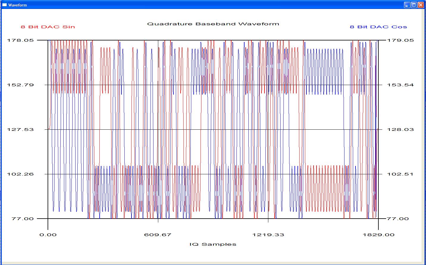
All internal simulation process's for packet creation can be viewed graphically.


Modulation Waveform Generator Module
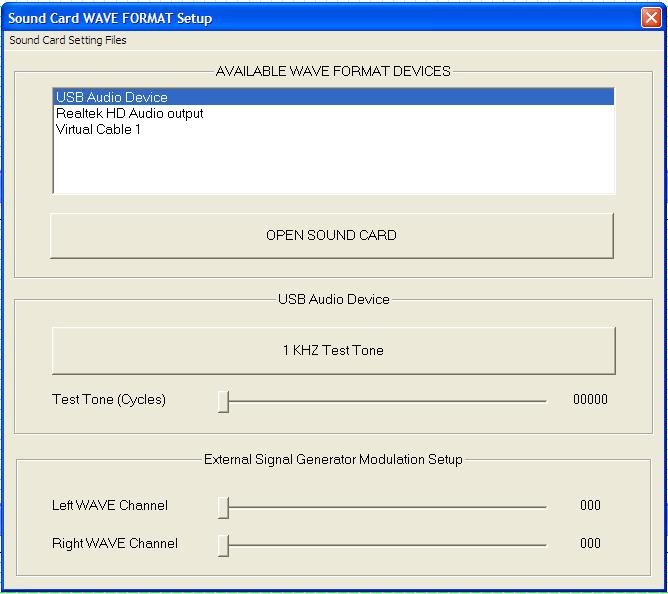
The Modulation Waveform Generator module that is embedded in the simulator creates all the required modulation waveforms as set out in IEC61993-2 paragraph 10.4 and IEC 62287 paragraph 10.4. It can perform the encoder requirement as set out in IEC61993-2 10.6. All original PMG1 legacy waveforms are supported. Further to this all M 1371-5 messages and waveforms are supported. It creates and generates 5 mutually exclusive AIS Targets. Standard Test Environment baseband waveforms can be output via the PC Sound Card Line Out to an external RF Signal Generator coupled to the EUT via a power pad.


Electronic Position Fixing Device Module
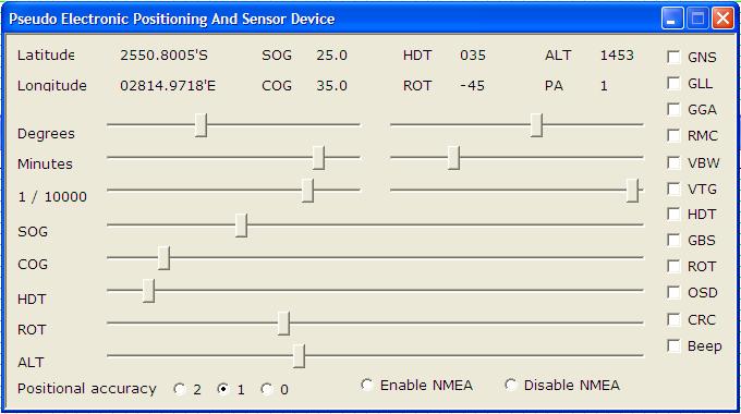
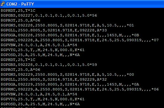
The Pseudo Electronic Position Fixing Device Dialogue provides an input method for formatting the NMEA defined GPS and SENSOR sentences. During parts of the verification the EUT GPS antenna is disconnected. The Pseudo Electronic Position Fixing Device is ported to the EUT sensor RS422 input. Dynamic external control of all positional and sensor information can be implemented using this method.
Own Profile Module
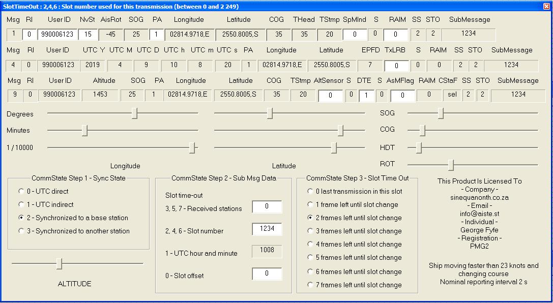
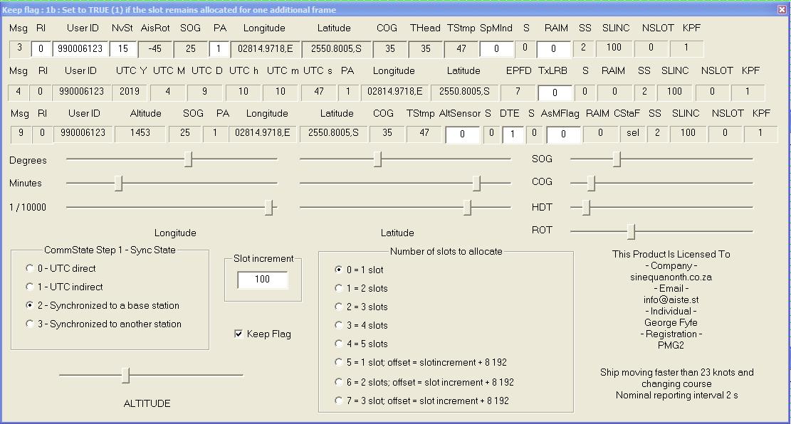
The Own Profile Dialogue provides an input method for formatting any packets generated using RATDMA as a mutually exclusive AIS Object. It can be set-up for SOTDMA or ITDMA communication states. Absolute control of generated base band or IQ VDL packet modulation data is available through this module. The OWN PROFILE allows right mouse click injection of any M 1371-5 packet into the Standard Test Environment. This allows realtime polling, channel managment etc or information excahnge to the Equipment Under Test via the externally modulated RF VDL signal.


Equipment Under Test Module
The EUT MMSI is used to identify and isolate all VDM / VDO messages generated in the Standard Test Environment by the equipment under test. This allows realtime analysis of all VDO / VDM traffic.
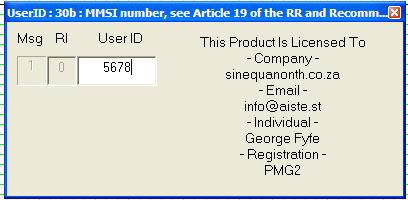
Standard Test Environment Module
The Standard Test Environment set-up provides an input method for formatting any packets generated automatically as mutually exclusive AIS Objects within the same VDL environment as the EUT. All 5 targets enter the VDL using ITDMA communication state formatting. After entry they will enter their respective EPFD dynamic navigation set-ups using SOTDMA communication state formatting. By respectively changing sensor data the dynamic navigation state of the target can be altered in real time. Absolute control of generated base band or IQ VDL packet data is available through this module.

VDL Analyser Timeline Module
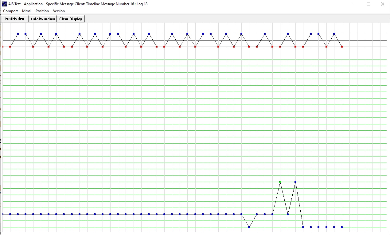
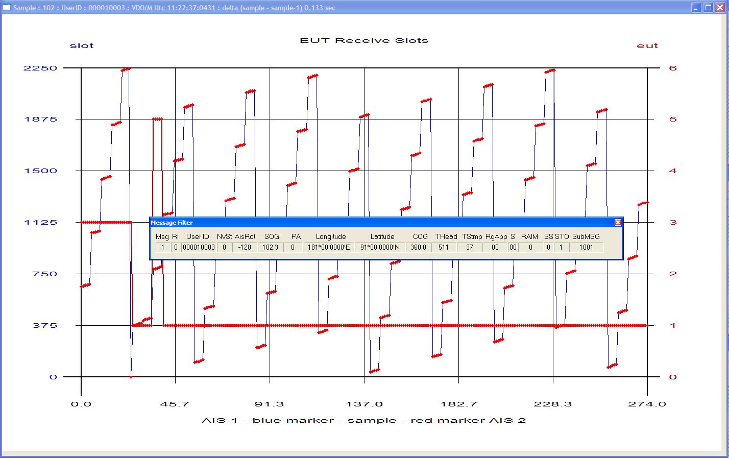
The AIS Developer Studio uses 3 timelines to display the following UTC time logged data. Signal Generator VDO / EUT VDO / EUT VDM or external receiver VDM information. The AIS Developer Studio will decode all required M 1371-5 messages. By placing the mouse cursor over the log indication and left clicking the mouse button, the relative message filter will show the decoded information that lies below the mouse cursor.
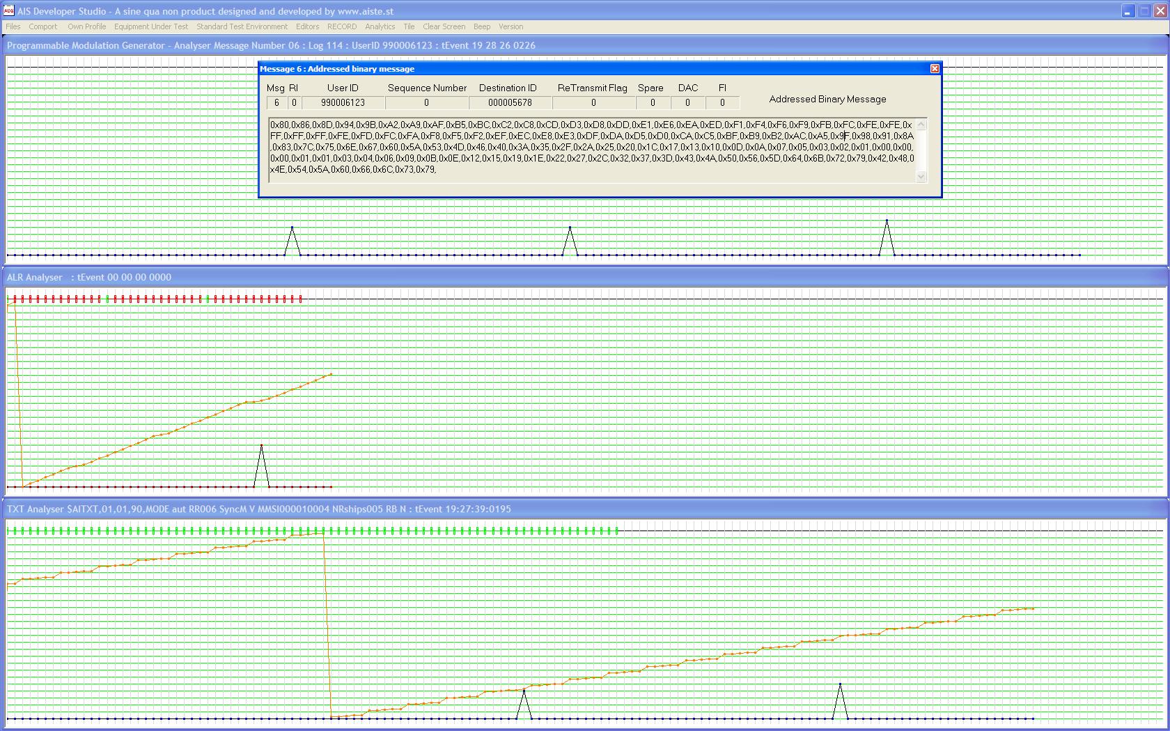
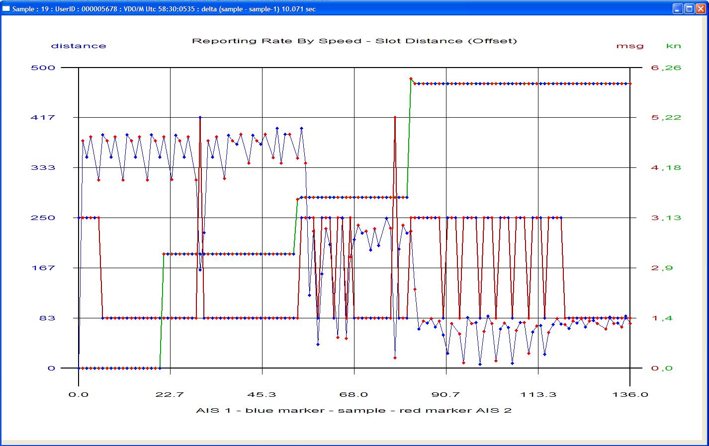
Pre – Verification Operational tests using Visual Analysis Module
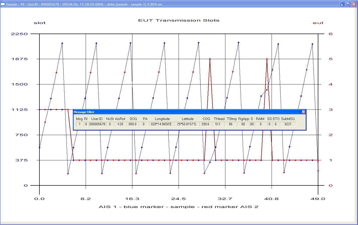
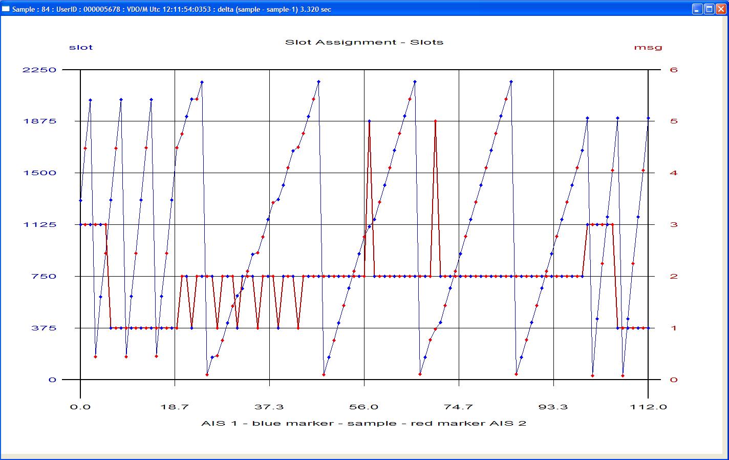
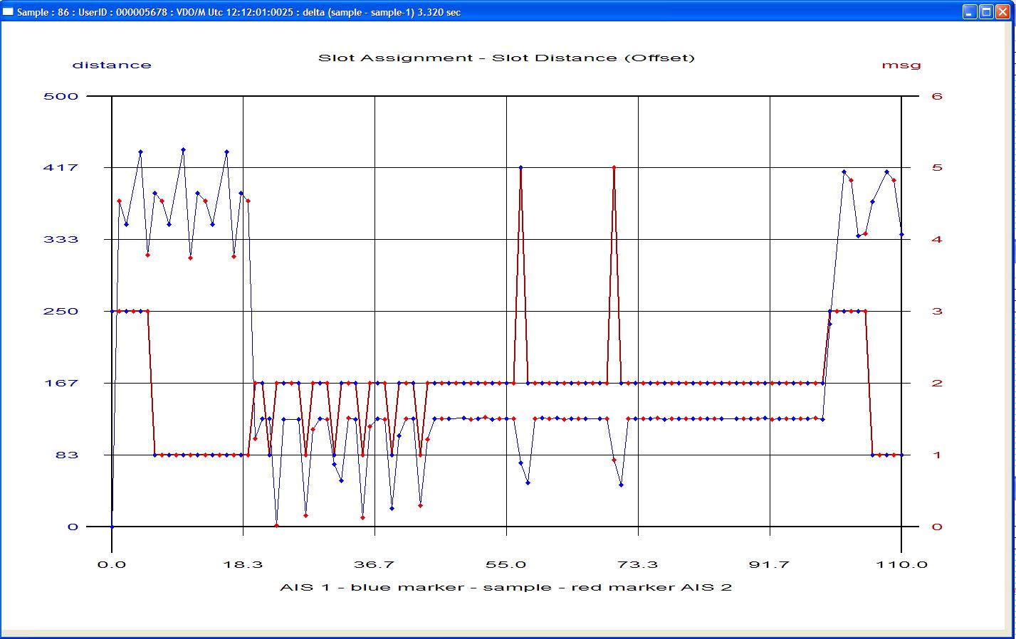
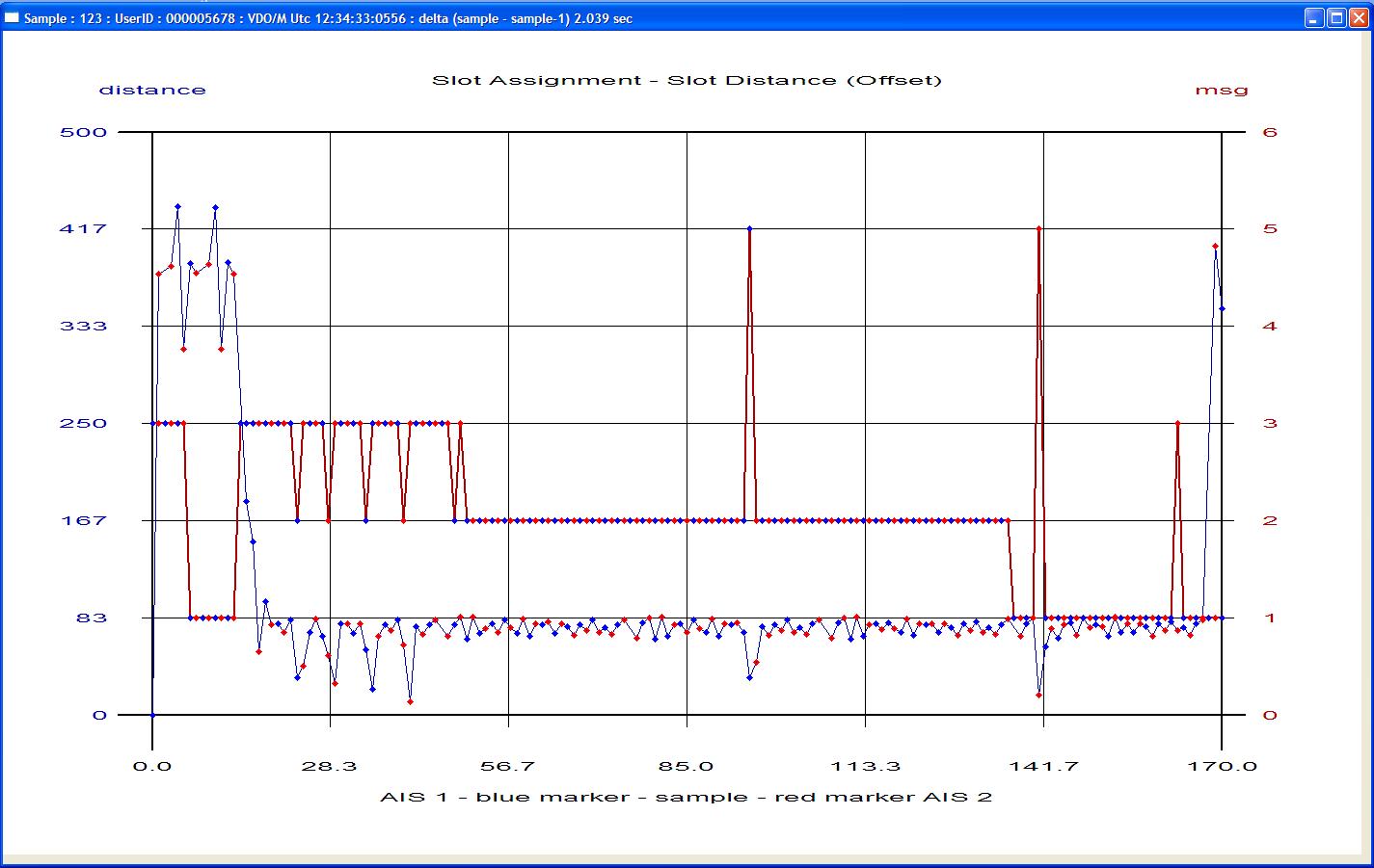
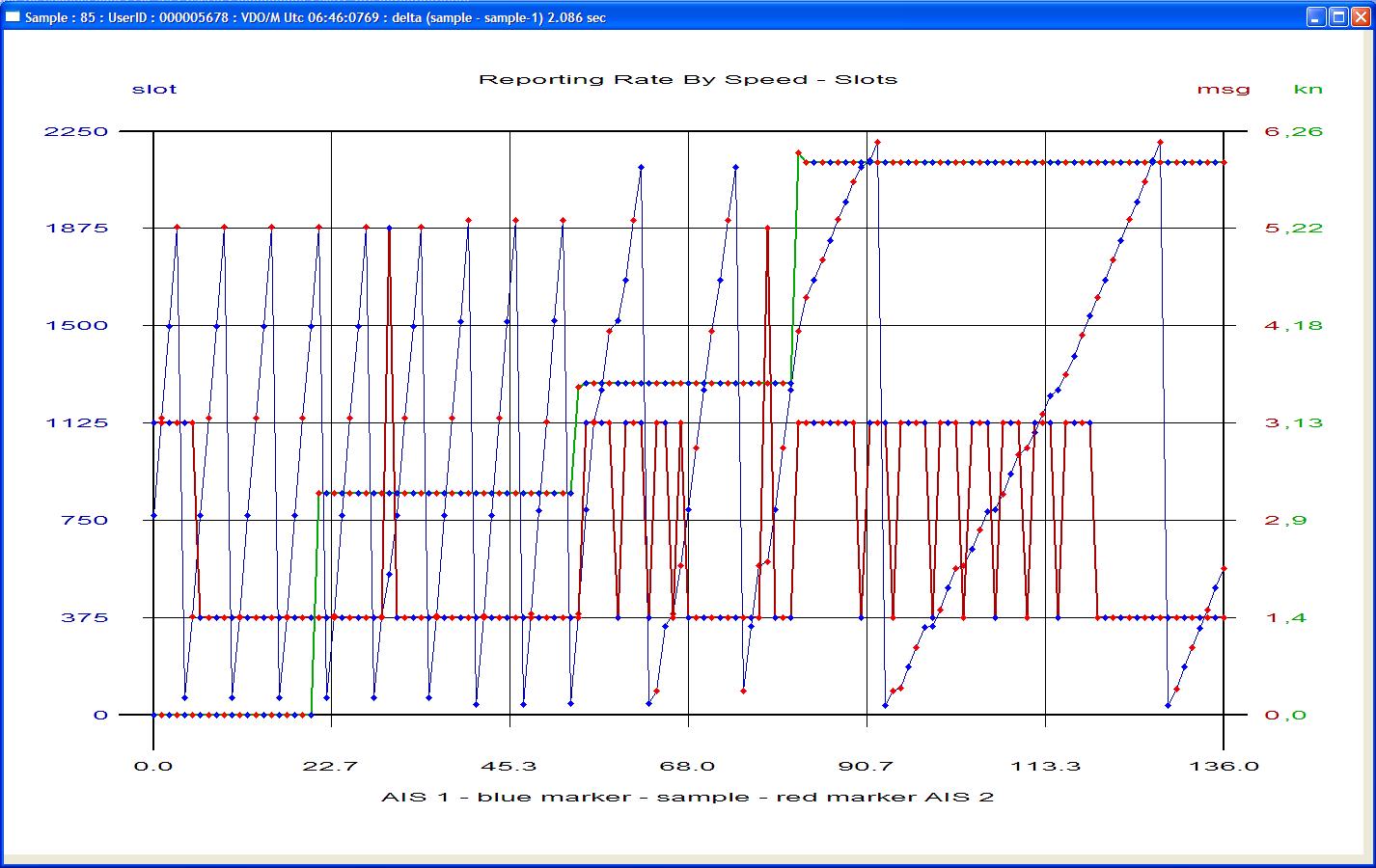
The OWN Profile, EUT VDO, EUT VDM ( or external receiver VDM ) time lines can be recorded and analised graphically.

LEGACY Equipment
AIS TEST continues to supply support and OEM re-verification of all Sine Qua Non legacy products.


AITS-R OEM Verification Certificate.
From 1 July 2014 legacy units may be returned to the "AIS Test" workshop for repair and re-verification according to original factory specifications..
How To Return A Unit To AIS Test Workshop.
1.Please contact us by email to obtain return procedure for repair and or re-verification .
2.For warranty service, enclose a scanned copy of your sales receipt with your email. If a copy of the original purchase receipt is not available, your product may be deemed out-of-warranty. .
3.If you are uncertain what product you own and or require a quote please contact us by email.
Contact
If you are interested in the AIS Developer Studio range of products, wish to order a product, pricing or just be kept in the loop. Please send an email to one of the following.
AIS TEST
28 Mustang Ave
Pierre Van Ryneveld
Centurion
Gauteng
South Africa
Tel: +27 07222 53467
www.aiste.st
Email : george@aiste.st
Email : george@sinequanonth.co.za
Email subject line : MUST containe the words "AIS Developer Studio"
Maritec Solutions (Pty) Ltd
Bay Ridge, Unit 60
53 Dolphin Crescent
Balito
4420
South Africa
+27 83 283 4198
info@maritec.co.za
https://www.maritec.co.za/contact-us
© 2019 Sine Qua Non - aiste.st


AIS PMG1/2 Programmable Modulation Generator

Where did it all begin.
Between 1992 and 1995 George Fyfe was contracted as a development partner to design and produce a RF transceiver technology, which Portnet Marine Data Systems would use as an identification and telemetry RF backbone for the full length of the South African coastline.
The hardware was known as the H25. In those early days the GPS 1PPS at times just vanished, so a secondary mechanism of TDMA lock was needed and the “Semaphore” method was developed. This was based on how many H25 stations were received at a specific location. This allowed a plurality of transmitting objects to share a TDMA structure in the cell they found themselves due to the “FM capture effect”. i.e. dBm, distance and time.
At the end of 1995, Portnet hosted the IALA Aids to Navigation conference in Cape Town. It was immediately recognised that parallel marine identification technologies had been developing across the seas. This Cape Town meeting was the pre-cursor to the inaugural IALA AIS meeting held early 1996 in Sweden.
Marine Data System represented the interests of George Fyfe at the early IALA AIS working group meetings. At discussions following these meetings it soon became clear that patents were frowned upon. As George Fyfe the original developer of the “TDMA Semaphore Concept” was at that time a co-patentee with Marine Data Systems , he sold his share of the development to Marine Data Systems. George Fyfe was rewarded with a five-year restraint of trade in AIS transponder technology. The semaphore technology went on to be included in ITU-M.1371.
With the restraint on AIS transponder technology in place, George Fyfe set his sights on developing production and front line AIS test sets. This resulted in the PMG1 and the AITS-R. These units were designed and produced at a time when there was no final AIS documentation available. All documents were working group draft documents.
Sine Qua Non went on to produce these industry leading hardware items for many years. And so the story continues with AIS TEST.
AIS Developer Studio Version 2 Overview
The AIS Developer Studio is a synergistic merger of software and hardware modules to create a general AIS development, production, integration and verification environment. It provides a value added service to all users of AIS equipment. The main objective of the system is to assist in providing different test and monitoring scenarios using the PC workstation as the main control object. It does this by providing interactive modules, which have been streamlined to produce verifiable outcomes. The Automatic Identification System (AIS Class A) is defined by the IMO and has been made a carriage requirement by the latest revision of SOLAS Chapter V. This does not only require the AIS to be installed, but also to provide information used for ship navigation. The AIS has been standardised by the ITU and IEC and is subject to type approval. In order to fulfil the reliability requirements of information exchange, product pre - verification and final verification must be done at all levels of development to ensure correct AIS inter operability.
The objective for the use of the AIS Developer Studio is to create a general VDL environment using a PC and optional external RF signal generator / power pad. Where the GMSK base-band is created and VDL, VDO and VDM data are easily analysed.
Our Design Philosophy
It is the intention of AISTE.ST through the current and further development of the AIS Developer Studio suite of components to continue to supply a cost effective method for development, production, integration and verification of protocols as used by AIS, ASM and VDE. It is the intention of AISTE.ST to supply upgrades to the AIS Developer suite user group as and when they become available. Users may subscribe to this upgrade service.
AIS Marine Radio Workstation Overview
 AIS Developer Studio provides a cost effective way of adding real time AIS base-band message generation capability and VDL analysis for production, repair, development and pre-verification to any RF Signal Generator or Radio Communications Test Set.
External modulation of the RF Signal Generator or Radio Communications Test Set using AIS Developer Studio PMG2 module allows real time operational verification of AIS transponder whilst providing VDL monitoring.
Evaluation of the AIS protocol stack of the equipment under test is accomplished using this method.
Data Interfaces
The AIS Developer studio uses the PC workstation hardware equipped with interfaces that allow opperation as a VDL Analyser, Pseudo Electronic Position Fixing Device – VDO / VDM EUT / VDM RX Presentation Interface (RS232 / RS422) : EUT Ship’s Sensors Inputs (Typically Gyro, GPS, COG and ROT Sensor) (RS422) : Other NMEA-compliant ship’s navigation equipment (RS232 RS422) :
A sound card line output may be applied to an external modulation signal input on your signal generator of choice. Baseband and IQ Baseband are offered
NTP / SNTP
The AIS Developer Studio makes use of NTP/SNTP network lock to obtain a relative UTC time base. All events are time stamped with the NTP/SNTP network lock. The accuracy of the UTC time stamp is dependent on your network lock of choice.
PMG2 Modulation Waveform Generator
- AIS Message Modulation
- Base band or IQ 9.6kbits/s GMSK
- IEC 61993 10.4.1 Standard Test Signal Number 1
- IEC 61993 10.4.2 Standard Test Signal Number 2
- IEC 61993 10.4.3 Standard Test Signal Number 3
- Legacy PMG Standard Test Signal Number 4
- IEC 62287 8.3.1 Standard Test Signal Number 1
- IEC 62287 8.3.1 Standard Test Signal Number 2
- IEC 62287 8.3.1 Standard Test Signal Number 3
- IEC 62287 8.3.1 Standard Test Signal Number 4
- IEC 62287 8.3.1 Standard Test Signal Number 5
- IEC 62320 6.2.4.1 Standard Test Signal Number 1
- IEC 62320 6.2.4.2 Standard Test Signal Number 2
- IEC 62320 6.2.4.3 Standard Test Signal Number 3
- IEC 62320 6.2.4.4 Standard Test Signal Number 4
- Real-time 5 target test environment
- Real-time creation of any one of 27 M.1371-5 VDL messages
- Real Time monitoring VDM, VDO, ALR, TXT
- Includes CCITT 511 bit pseudo-random test pattern
- VDO string generation
- DSC Modulation
- V23 Modulation
- Standard DSC test signal as defined in 10.4.1
AIS VDL Analyser
- 150 tracks per timeline
- Horizontal time grid
- Vertical message grid
- Test Environment activity
- Own Profile VDO activity
- Realtime EUT VDO activity
- Realtime EUT VDM activity
- 27 M.1371-5 messages
- Realtime $AIABK monitoring
- Realtime $AIALR monitoring & manual ACK
- Realtime $AITXT monitoring
EPFD Sensor Strings (RS422 Output)
- GNS
- GLL
- GGA
- RMC
- VBW
- VTG
- HDT
- GBS
- ROT
- OSD
- DTM
- 1PPS BEEP
Standard Test Environment
- Pseudo Electronic Position Fixing Device providing exclusive direct control over GPS, COG, SOG, HDT, ROT for each individual target.
- Dynamic navigation derived from PEPFD settings.
- Detection of non valid 6 bit TEXT characters.
- Global setting of fault indication – (PC beep).
- Tracking, static and voyage data.
- Descriptions for each edit window are auto provided.
- Auto profile 5 targets using licence defaults or individual.
- SETUP 5 AIS Targets
- START 5 AIS Targets
- STOP 5 AIS Targets
-
Download
Upgrades
Waveforms
All internal simulation process's for packet creation can be viewed graphically.


Modulation Waveform Generator Module
The Modulation Waveform Generator module that is embedded in the simulator creates all the required modulation waveforms as set out in IEC61993-2 paragraph 10.4 and IEC 62287 paragraph 10.4. It can perform the encoder requirement as set out in IEC61993-2 10.6. All original PMG1 legacy waveforms are supported. Further to this all M 1371-5 messages and waveforms are supported. It creates and generates 5 mutually exclusive AIS Targets. Standard Test Environment baseband waveforms can be output via the PC Sound Card Line Out to an external RF Signal Generator coupled to the EUT via a power pad.


Electronic Position Fixing Device Module
The Pseudo Electronic Position Fixing Device Dialogue provides an input method for formatting the NMEA defined GPS and SENSOR sentences. During parts of the verification the EUT GPS antenna is disconnected. The Pseudo Electronic Position Fixing Device is ported to the EUT sensor RS422 input. Dynamic external control of all positional and sensor information can be implemented using this method.


Own Profile Module
The Own Profile Dialogue provides an input method for formatting any packets generated using RATDMA as a mutually exclusive AIS Object. It can be set-up for SOTDMA or ITDMA communication states. Absolute control of generated base band or IQ VDL packet modulation data is available through this module. The OWN PROFILE allows right mouse click injection of any M 1371-5 packet into the Standard Test Environment. This allows realtime polling, channel managment etc or information excahnge to the Equipment Under Test via the externally modulated RF VDL signal.


Equipment Under Test Module
The EUT MMSI is used to identify and isolate all VDM / VDO messages generated in the Standard Test Environment by the equipment under test. This allows realtime analysis of all VDO / VDM traffic.

Standard Test Environment Module
The Standard Test Environment set-up provides an input method for formatting any packets generated automatically as mutually exclusive AIS Objects within the same VDL environment as the EUT. All 5 targets enter the VDL using ITDMA communication state formatting. After entry they will enter their respective EPFD dynamic navigation set-ups using SOTDMA communication state formatting. By respectively changing sensor data the dynamic navigation state of the target can be altered in real time. Absolute control of generated base band or IQ VDL packet data is available through this module.

VDL Analyser Timeline Module
The AIS Developer Studio uses 3 timelines to display the following UTC time logged data. Signal Generator VDO / EUT VDO / EUT VDM or external receiver VDM information. The AIS Developer Studio will decode all required M 1371-5 messages. By placing the mouse cursor over the log indication and left clicking the mouse button, the relative message filter will show the decoded information that lies below the mouse cursor.

Pre – Verification Operational tests using Visual Analysis Module
The OWN Profile, EUT VDO, EUT VDM ( or external receiver VDM ) time lines can be recorded and analised graphically.


LEGACY Equipment
AIS TEST continues to supply support and OEM re-verification of all Sine Qua Non legacy products.


AITS-R OEM Verification Certificate.
From 1 July 2014 legacy units may be returned to the "AIS Test" workshop for repair and re-verification according to original factory specifications..
How To Return A Unit To AIS Test Workshop.
1.Please contact us by email to obtain return procedure for repair and or re-verification .
2.For warranty service, enclose a scanned copy of your sales receipt with your email. If a copy of the original purchase receipt is not available, your product may be deemed out-of-warranty. .
3.If you are uncertain what product you own and or require a quote please contact us by email.
Contact
If you are interested in the AIS Developer Studio range of products, wish to order a product, pricing or just be kept in the loop. Please send an email to one of the following.
AIS TEST
28 Mustang Ave
Pierre Van Ryneveld
Centurion
Gauteng
South Africa
Tel: +27 07222 53467
www.aiste.st
Email : george@aiste.st
Email : george@sinequanonth.co.za
Email subject line : MUST containe the words "AIS Developer Studio"
Maritec Solutions (Pty) Ltd
Bay Ridge, Unit 60
53 Dolphin Crescent
Balito
4420
South Africa
+27 83 283 4198
info@maritec.co.za
https://www.maritec.co.za/contact-us
© 2019 Sine Qua Non - aiste.st

Where did it all begin.
Between 1992 and 1995 George Fyfe was contracted as a development partner to design and produce a RF transceiver technology, which Portnet Marine Data Systems would use as an identification and telemetry RF backbone for the full length of the South African coastline.
The hardware was known as the H25. In those early days the GPS 1PPS at times just vanished, so a secondary mechanism of TDMA lock was needed and the “Semaphore” method was developed. This was based on how many H25 stations were received at a specific location. This allowed a plurality of transmitting objects to share a TDMA structure in the cell they found themselves due to the “FM capture effect”. i.e. dBm, distance and time.
At the end of 1995, Portnet hosted the IALA Aids to Navigation conference in Cape Town. It was immediately recognised that parallel marine identification technologies had been developing across the seas. This Cape Town meeting was the pre-cursor to the inaugural IALA AIS meeting held early 1996 in Sweden.
Marine Data System represented the interests of George Fyfe at the early IALA AIS working group meetings. At discussions following these meetings it soon became clear that patents were frowned upon. As George Fyfe the original developer of the “TDMA Semaphore Concept” was at that time a co-patentee with Marine Data Systems , he sold his share of the development to Marine Data Systems. George Fyfe was rewarded with a five-year restraint of trade in AIS transponder technology. The semaphore technology went on to be included in ITU-M.1371.
With the restraint on AIS transponder technology in place, George Fyfe set his sights on developing production and front line AIS test sets. This resulted in the PMG1 and the AITS-R. These units were designed and produced at a time when there was no final AIS documentation available. All documents were working group draft documents.
Sine Qua Non went on to produce these industry leading hardware items for many years. And so the story continues with AIS TEST.
AIS Developer Studio Version 2 Overview
The AIS Developer Studio is a synergistic merger of software and hardware modules to create a general AIS development, production, integration and verification environment. It provides a value added service to all users of AIS equipment. The main objective of the system is to assist in providing different test and monitoring scenarios using the PC workstation as the main control object. It does this by providing interactive modules, which have been streamlined to produce verifiable outcomes. The Automatic Identification System (AIS Class A) is defined by the IMO and has been made a carriage requirement by the latest revision of SOLAS Chapter V. This does not only require the AIS to be installed, but also to provide information used for ship navigation. The AIS has been standardised by the ITU and IEC and is subject to type approval. In order to fulfil the reliability requirements of information exchange, product pre - verification and final verification must be done at all levels of development to ensure correct AIS inter operability.
The objective for the use of the AIS Developer Studio is to create a general VDL environment using a PC and optional external RF signal generator / power pad. Where the GMSK base-band is created and VDL, VDO and VDM data are easily analysed.
Our Design Philosophy
It is the intention of AISTE.ST through the current and further development of the AIS Developer Studio suite of components to continue to supply a cost effective method for development, production, integration and verification of protocols as used by AIS, ASM and VDE. It is the intention of AISTE.ST to supply upgrades to the AIS Developer suite user group as and when they become available. Users may subscribe to this upgrade service.
AIS Marine Radio Workstation Overview
External modulation of the RF Signal Generator or Radio Communications Test Set using AIS Developer Studio PMG2 module allows real time operational verification of AIS transponder whilst providing VDL monitoring.
Evaluation of the AIS protocol stack of the equipment under test is accomplished using this method.
Data Interfaces
The AIS Developer studio uses the PC workstation hardware equipped with interfaces that allow opperation as a VDL Analyser, Pseudo Electronic Position Fixing Device – VDO / VDM EUT / VDM RX Presentation Interface (RS232 / RS422) : EUT Ship’s Sensors Inputs (Typically Gyro, GPS, COG and ROT Sensor) (RS422) : Other NMEA-compliant ship’s navigation equipment (RS232 RS422) :
A sound card line output may be applied to an external modulation signal input on your signal generator of choice. Baseband and IQ Baseband are offered
NTP / SNTP
The AIS Developer Studio makes use of NTP/SNTP network lock to obtain a relative UTC time base. All events are time stamped with the NTP/SNTP network lock. The accuracy of the UTC time stamp is dependent on your network lock of choice.
PMG2 Modulation Waveform Generator
- AIS Message Modulation
- Base band or IQ 9.6kbits/s GMSK
- IEC 61993 10.4.1 Standard Test Signal Number 1
- IEC 61993 10.4.2 Standard Test Signal Number 2
- IEC 61993 10.4.3 Standard Test Signal Number 3
- Legacy PMG Standard Test Signal Number 4
- IEC 62287 8.3.1 Standard Test Signal Number 1
- IEC 62287 8.3.1 Standard Test Signal Number 2
- IEC 62287 8.3.1 Standard Test Signal Number 3
- IEC 62287 8.3.1 Standard Test Signal Number 4
- IEC 62287 8.3.1 Standard Test Signal Number 5
- IEC 62320 6.2.4.1 Standard Test Signal Number 1
- IEC 62320 6.2.4.2 Standard Test Signal Number 2
- IEC 62320 6.2.4.3 Standard Test Signal Number 3
- IEC 62320 6.2.4.4 Standard Test Signal Number 4
- Real-time 5 target test environment
- Real-time creation of any one of 27 M.1371-5 VDL messages
- Real Time monitoring VDM, VDO, ALR, TXT
- Includes CCITT 511 bit pseudo-random test pattern
- VDO string generation
- DSC Modulation
- V23 Modulation
- Standard DSC test signal as defined in 10.4.1
AIS VDL Analyser
- 150 tracks per timeline
- Horizontal time grid
- Vertical message grid
- Test Environment activity
- Own Profile VDO activity
- Realtime EUT VDO activity
- Realtime EUT VDM activity
- 27 M.1371-5 messages
- Realtime $AIABK monitoring
- Realtime $AIALR monitoring & manual ACK
- Realtime $AITXT monitoring
EPFD Sensor Strings (RS422 Output)
- GNS
- GLL
- GGA
- RMC
- VBW
- VTG
- HDT
- GBS
- ROT
- OSD
- DTM
- 1PPS BEEP
Standard Test Environment
- Pseudo Electronic Position Fixing Device providing exclusive direct control over GPS, COG, SOG, HDT, ROT for each individual target.
- Dynamic navigation derived from PEPFD settings.
- Detection of non valid 6 bit TEXT characters.
- Global setting of fault indication – (PC beep).
- Tracking, static and voyage data.
- Descriptions for each edit window are auto provided.
- Auto profile 5 targets using licence defaults or individual.
- SETUP 5 AIS Targets
- START 5 AIS Targets
- STOP 5 AIS Targets
Download
Upgrades
Waveforms
All internal simulation process's for packet creation can be viewed graphically.
Modulation Waveform Generator Module
The Modulation Waveform Generator module that is embedded in the simulator creates all the required modulation waveforms as set out in IEC61993-2 paragraph 10.4 and IEC 62287 paragraph 10.4. It can perform the encoder requirement as set out in IEC61993-2 10.6. All original PMG1 legacy waveforms are supported. Further to this all M 1371-5 messages and waveforms are supported. It creates and generates 5 mutually exclusive AIS Targets. Standard Test Environment baseband waveforms can be output via the PC Sound Card Line Out to an external RF Signal Generator coupled to the EUT via a power pad.
Electronic Position Fixing Device Module
The Pseudo Electronic Position Fixing Device Dialogue provides an input method for formatting the NMEA defined GPS and SENSOR sentences. During parts of the verification the EUT GPS antenna is disconnected. The Pseudo Electronic Position Fixing Device is ported to the EUT sensor RS422 input. Dynamic external control of all positional and sensor information can be implemented using this method.
Own Profile Module
The Own Profile Dialogue provides an input method for formatting any packets generated using RATDMA as a mutually exclusive AIS Object. It can be set-up for SOTDMA or ITDMA communication states. Absolute control of generated base band or IQ VDL packet modulation data is available through this module. The OWN PROFILE allows right mouse click injection of any M 1371-5 packet into the Standard Test Environment. This allows realtime polling, channel managment etc or information excahnge to the Equipment Under Test via the externally modulated RF VDL signal.
Equipment Under Test Module
The EUT MMSI is used to identify and isolate all VDM / VDO messages generated in the Standard Test Environment by the equipment under test. This allows realtime analysis of all VDO / VDM traffic.
Standard Test Environment Module
The Standard Test Environment set-up provides an input method for formatting any packets generated automatically as mutually exclusive AIS Objects within the same VDL environment as the EUT. All 5 targets enter the VDL using ITDMA communication state formatting. After entry they will enter their respective EPFD dynamic navigation set-ups using SOTDMA communication state formatting. By respectively changing sensor data the dynamic navigation state of the target can be altered in real time. Absolute control of generated base band or IQ VDL packet data is available through this module.

VDL Analyser Timeline Module
The AIS Developer Studio uses 3 timelines to display the following UTC time logged data. Signal Generator VDO / EUT VDO / EUT VDM or external receiver VDM information. The AIS Developer Studio will decode all required M 1371-5 messages. By placing the mouse cursor over the log indication and left clicking the mouse button, the relative message filter will show the decoded information that lies below the mouse cursor.
Pre – Verification Operational tests using Visual Analysis Module
The OWN Profile, EUT VDO, EUT VDM ( or external receiver VDM ) time lines can be recorded and analised graphically.
LEGACY Equipment
AIS TEST continues to supply support and OEM re-verification of all Sine Qua Non legacy products.


AITS-R OEM Verification Certificate.
From 1 July 2014 legacy units may be returned to the "AIS Test" workshop for repair and re-verification according to original factory specifications..
How To Return A Unit To AIS Test Workshop.
1.Please contact us by email to obtain return procedure for repair and or re-verification .
2.For warranty service, enclose a scanned copy of your sales receipt with your email. If a copy of the original purchase receipt is not available, your product may be deemed out-of-warranty. .
3.If you are uncertain what product you own and or require a quote please contact us by email.
Contact
If you are interested in the AIS Developer Studio range of products, wish to order a product, pricing or just be kept in the loop. Please send an email to one of the following.
AIS TEST
28 Mustang AvePierre Van Ryneveld
Centurion
Gauteng
South Africa
Tel: +27 07222 53467
www.aiste.st
Email : george@aiste.st
Email : george@sinequanonth.co.za
Email subject line : MUST containe the words "AIS Developer Studio"
Maritec Solutions (Pty) Ltd
Bay Ridge, Unit 6053 Dolphin Crescent
Balito
4420
South Africa
+27 83 283 4198
info@maritec.co.za
https://www.maritec.co.za/contact-us
© 2019 Sine Qua Non - aiste.st